ReWire for Verilog Programmers
This section presents a Verilog design for a UART (created by some AI agent) and rewrites it in ReWire. The structure of the resulting ReWire specification follows the structure of the Verilog design very closely. The codes for the UART is:
Throughout this section, I’ll focus on the uart_tx routine defined in rtl_uart.sv and demonstrate how Verilog code is translated into corresponding ReWire definitions. Recall from the beginning of this chapter that the type ReacT i o (StateT s Identity) () corresponds to a Mealy machine:
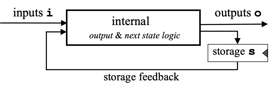
The first thing to do is determine what the types i, o, and s are for the UART.
Inputs
In the Verilog specification, here is the snippet defining the inputs:
input clk,
input rst,
input tx_start,
input [7:0] tx_data,
Corresponding to this is the ReWire declaration I. Only the clk signal is left out because it is already encoded by the reactive resumption monad structure. The first two inputs then are rst and tx_start, which are both Bits, and tx_data, which is an 8-bit word:
data I = I { rst      :: Bit
           , tx_start :: Bit
           , tx_data  :: W 8 }
FSM States
The UART transfer routing has four states, each of which is explicitly named:
// FSM States
localparam IDLE      = 2'b00;
localparam START_BIT = 2'b01;
localparam DATA_BITS = 2'b10;
localparam STOP_BIT  = 2'b11;
In ReWire, these are expressed as a data declaration:
data State = IDLE | START_BIT | DATA_BITS | STOP_BIT
Register File
Anything declared as a reg in Verilog is a register, some (tx_pin and tx_done) being also connected to outputs.
output reg tx_pin,
output reg tx_done
reg [1:0] state;
reg [15:0] clk_count;
reg [2:0] bit_index;
reg [7:0] data_reg;
For each reg above, there is a corresponding tag in the following type RF; note that ``RF uses Haskell’s record syntax.
data RF = RF { state     :: State
             , clk_count :: W 16
             , bit_index :: W 3
             , data_reg  :: W 8
             , tx_pin    :: Bit
             , tx_done   :: Bit }
Initial Register File
state     <= IDLE;
tx_pin    <= 1'b1;
tx_done   <= 1'b0;
clk_count <= 0;
bit_index <= 0;
rf0 :: RF
rf0 = RF { state     = IDLE
         , tx_pin    = True
         , tx_done   = False
         , clk_count = lit 0
         , bit_index = lit 0
         , data_reg  = lit 0
         }
Output Type
The following code defines the two outputs in rtl_uart.sv:
output reg tx_pin,
output reg tx_done
Therefore, the output type will be (Bit , Bit).